Showing posts with label Texture. Show all posts

Saturday, July 22, 2017

Texture Animation

This approach to animating textures is well documented via videos.  Here is a written procedure of the standard approach for using the UV Warp modifier to achieve a texture animation.

This technique is found in characters like Pocoyo or the Lego movies.


Saturday, July 8, 2017

Texture Map - External Coloring

In this entry I'll cover how to create a texture based on the unwrapped UV map.  In this case, I wanted to create the waffle cone volcano in a game I was making.  In some cases it makes more sense to attempt to paint directly in the viewfinder.  For that see my other entry:  Texture Painting.  In this case with a specific uv unwrapping in mind, I wanted to modify the mapped texture.


The first step is to unwrap the UVs on the object.  Then with a new empty image created, Bake the current material into that image.  Render Tab > Bake panel > Bake button  (shown below).

Friday, September 21, 2012

Material Mask - Cycles

This entry will cover the function of creating a material mask using an image texture.  Our starting model is a simple sub-surfaced cylinder with a uv-mapped texture on it.


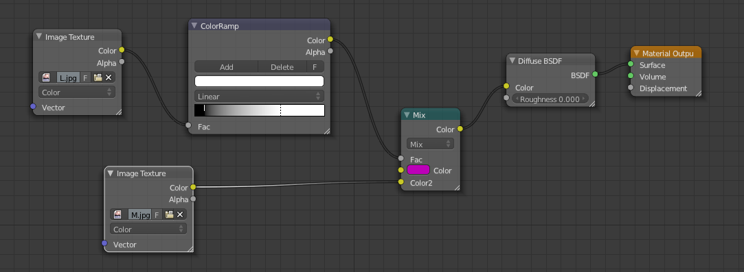
Using the following material node setup, we essentially are taking a second texture and masking out parts based on luminance.  A bright magenta is used to show what would normally be another texture showing through.  The ColorRamp node converts the output of the texture to black and white, while the sliders allow you to control what parts of the texture will show through.

An example of the cylinder now masked showing some magenta areas through.

Taking this node setup further, the output from the ColorRamp can be fed into a Mix Shader to also act as a mask for another shader (in this example a Glossy Shader).  A Mix Color node must be placed in between to control the strength of the second shader.  The second color of the Mix Color node must be set to black, acting like a scale between black and the full white from the ramp.

The result of this setup is as shown below, where the glossy is only affecting the areas that are masked per say.

Friday, May 25, 2012

Specular Texture

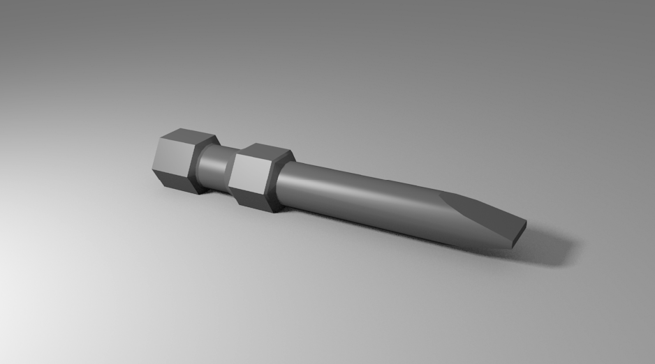
This entry covers the topic of Specular Textures.  Essentially it is applying a grayscale texture as a specular map, to give an object a non-uniform specularity.  To demonstrate, I have a model of a hex bit that has a single material that is a solid gray with the standard uniform specularity.  I'll be adding a stretched cloud texture to give the bit a more brushed metal look.


The first step is to remove the material specularity.  This can be done by dropping the Intensity to 0.  The Hardness should me maintained however, or possibly increased.

Next create a new texture for this material.  Regardless of what you use for the texture, be it an image or a built-in Blender texture, essentially the main parameters to change are in the Influence section.  Uncheck the Color in Diffuse and check the Intensity in the Specular.  Now the light values of the texture will provide high specularity while the dark parts will provide less.

From here, the nature of the specularity is up to your creativity.  I used the following settings with the built-in cloud texture to produce the brushed metal look in the final render below.

Final render with the specular map applied.  The metal almost seems to have a normal map feel, but it's purely just specular map reflection.

Sunday, May 20, 2012

Texture Atlas


This entry will cover a very important technique for providing improved texture detail on meshes for gaming purposes while minimizing the number of materials needed.  In gaming it is very important to have as few materials as possible, as every unique material in a mesh requires a separate 'Draw Call'.  So if possible you want to combine your materials into one single map (or Texture Atlas).  

In our example I've started with a sphere that has been UV unwrapped via a seam [CTRL+E] around the equator. 
I applied two different materials, one a brick image and one a rug image.  So to begin, we have a single mesh wit two materials, each with their own image texture UV mapped onto the sphere.  The goal is to combine these two materials into one.

To combine the two, we will essentially be baking the rendered textures onto a new UV map on the sphere. So on the mesh tab, press the [+] button on the UV Maps panel, and name the new map.  In this image I named it 'BakedUVs' but later I'll refer to it as just 'Baked'.

Note: For the baking to work be sure that the new UV map 'BakedUVs' is selected.

At this point, go to the UV Editor [CTRL+LEFT] view, you can view the UV unwrapping for this new UV map.  You can change it, but I've had the most success just leaving it the same as the original.  However, you do need to create a new image.  This should appear as a black square behind your map.

Also note that the mesh must be selected (highlighted orange) while in this view (as shown below).


Next is the baking, but before you move onto this step, in the case of a sphere, to make the texture looking cleaner and smoother, I applied a subsurf and smooth shading to it.  The baked textured will be based on the render, so any of these features will be applied by the bake.

Go to the Render Tab, and at the very bottom you'll find the Bake section.  You don't need to change any parameters just hit Bake.


If you return to the UV Editor window you should now be able to see your new texture baked onto the new image.  This now has both materials on one texture, and the lighting from the rendered scene can now be seen (most obviously on the brick side of the texture).  

Note: Make sure to save this new image.


The following steps will simply show how to reduce your materials down to one to be transferred into a gaming engine such as Unity.  You may want to save as a different filename to preserve the original two-materials in case you want to change it and re-bake.

The first step is to remove the other (original) UV map and just keep the new baked UV map.

The next step is to create a new single material, so the other two can now be removed.

Finally, on the new material, add a new texture and assign the new Texture Atlas which was created from the bake, and make sure the new UV Map is selected.

 Now when rendered, you have both textures/materials applied while using only one material.

The ultimate benefit now is if you export the file to an FBX and transfer the model with its texture into Unity, you can get the same texture detail, now with one UV map and one material.  Note in the stats window that the draw call is only 1.

Friday, April 6, 2012

Transparent Decal

This entry will cover a simple approach to applying an image (PNG) with transparency to a material that has color.  The image with transparency is the eyes seen below.


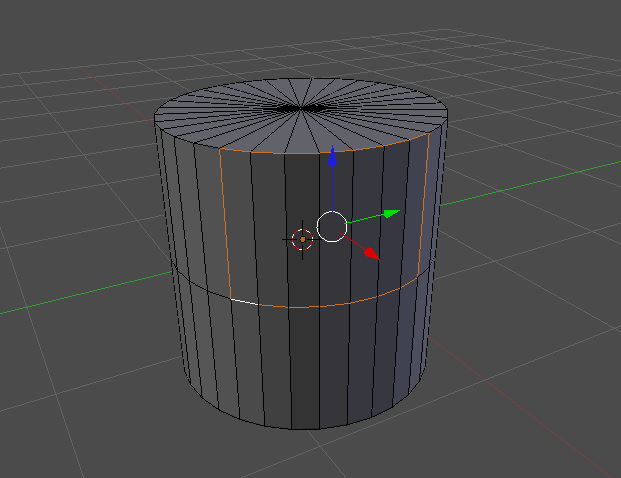
We'll be applying these eyes to a segment of the cylinder, and we've isolated the segment by highlighting the surrounding edges as shown below.

These edges will be made into a Seam so that we can find them in the unwrapped map easier.  This can be done with [Ctrl + E], and selecting Mark Seam.  Note that breaking the mesh into UV islands is not recommended for models to be used in real-time (gaming) applications.

Once the vertices are marked and the mesh is unwrapped using the standard [U] and Unwrap, moving over to the UV/Editor [Ctrl + LEFT], should show a UV map similar to the one below.  Our seams are now very obvious to find.

Since we only want the image to display in our segment, we'll enlarge it accordingly and move all the other elements of the mesh outside of the image.

Back in the standard view, create a new material for the cylinder, and add a new texture.  In the texture properties, all you need to do is set the Extension to Clip, and ensure the Coordinates are UV and the Projection is Flat.  No further fiddling with transparency is needed. The transparency is covered automatically.

The final render with the eyes textured onto the cylinder.

Tuesday, March 20, 2012

Baking Normals

This entry will be covering the concept of Normal Baking.  This is very useful for adding very high detail to very simple geometry.  This is very important for applications such as gaming where high detail, but low polygons are required. This example will take the simplest approach to Normal Baking, and that's simply adding texture to a plane.

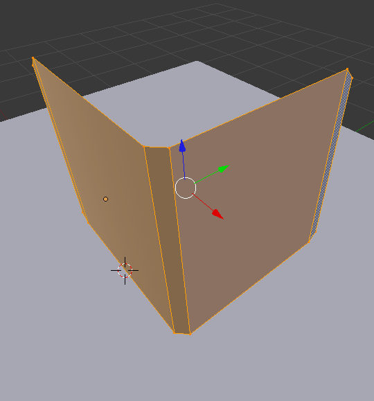
So first off, the detail is created with an actual mesh.  in this case, I created a simple raised edge surface, which is the same size as the regular plane below it.

The blank plane below is the target object which will receive the map baking.  The normal map will need to be projected onto the UV map, so the receiving plane needs to be unwrapped [U].

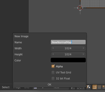
In the UV Editor View, create a new image and name it something appropriate relating to normal maps.

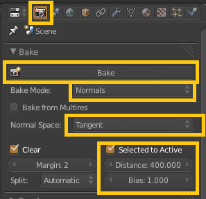
Next is baking, but before this is done.  Back in the 3D View, make sure to select the detailed mesh and the blank receiving mesh, in that order.  Then in the Render palette, set the following parameters in the Bake section.  Note: The values defined here were specified in a CG Cookie Tutorial i saw.

When you finally click Bake, back in the UV Edit View, you should now see the the normal map created as an image on the receiving plane.  Save this image somewhere on your harddrive.

Next we'll apply that normal map to the receiving plane so that it is visible.
Follow the next sequence of parameter settings for the Texture of the plane, as would be standard applied.


Finally, to be able to see the texture in action in the 3D View, set the View Mode to Texture, and in the Properties Panel [N], set the following Shading settings.


Now in the 3D view, you should be able to see the new normal map in all its gory.  It will update in real-time as you move and change the lighting of the scene.  And as was originally stated, all this detail is simply a normal map on a single plane (quad).

Monday, February 20, 2012

UV Follow Quads

This entry will show how to use the UV unwrapping technique called Follow Active Quads.  This works particularly well with walls or beveled surfaces which have a continuous texture.  So for this example, we'll apply a brick texture to this beveled wall.


In Edit Mode [TAB], select all the vertices and bring up the UV Mapping menu [u] and select Follow Active Quads.

When switching over to the UV Edit mode [Ctrl + Left], you'll notice that the quads are now nicely and adjacently aligned in the view.

From here, add a new material to the mesh, and set the Color to an Image Texture.  Select the desired image texture, in this case a brick wall.  When you navigate back to the UV Edit view, you should see that texture available in the view for manipulating the vertices with respect to the image.

The final render for this example is three instances of the wall with the brick texture.


Monday, February 13, 2012

Weight Paint Displacement

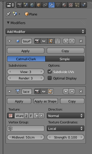
This entry goes over the process of weight painting or controlling the effect of a displacement modifier among a mesh.  So first we start out with a grid mesh, whose surface has been deformed via a displacement modifier seeded by a Cloud texture.


 Sub-Surf was also applied to improve the appearance.

A quick render of this will show the displacement is applied all over the mesh.  Now, if we want only some parts of the mesh to affected and others not, we can do this by defining a Vertex Group and applying weight painting.

So first we define a vertex group.  The one I'm going to use here is SecondWeight.  The highlighted vertex group will be the one that receives the weight painting.

Switching over to weight-paint mode, we can now paint onto the mesh to apply the 'strength' of the modifier to different parts of the mesh.  Blue represents zero effect, and Red represents full effect.

From the pattern I've painted, the camera should see a long line of strong displacement a little to the right of the camera stretching toward the horizon, while there is less influence on the sides.

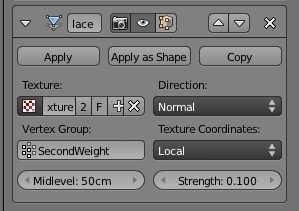
After painting is complete, set the Vertex Group in the Displacement modifier.

The effect of the weight paint (vertex group) should be apparent within the mesh even before rendering.

Rendering shows what we expect.  Strong displacement to the right of the camera, and softer displacement elsewhere.