Showing posts with label Modifier. Show all posts

Sunday, February 7, 2016

Array Constrained Rotation

This entry will cover using the Array Modifier as well as a rotation Constraint to make a rotationally, symmetrical object, by editing only a small part of the mesh.  The example given is with creating a snowflake.
First step is to create an Empty.  You can use any type, i used a cone because the tutorial i watched did so.

Thursday, November 12, 2015

Stacking Modifiers

Although stacking modifiers on a mesh is a fairly elementary concept, here I'll show the power of stacking modifiers to make a very elaborate design from a very simple base mesh.  This came about when I made a nerf trophy that would be 3D printed.  The red region (honeycomb shape) is what will be made.

Saturday, June 16, 2012

Build Modifier

This quick entry demonstrates the Build Modifier.  It is very simple and has a neat animation effect.  When added, you'll first notice that your mesh disappears.  This is because all the vertices are hidden, and will be sequentially revealed when the animation is played [ALT + A].

In the properties panel, there are a few controls.  The Start and Length are used to control the timing and length of the animation, and the Randomize allows the sequence of vertices to appear randomly.  

To demonstrate this neat effect, I downloaded a motorcycle from Blend Swap, combined all the separate parts into a single mesh by joining [CTRL+J], and added this modifier.  Since I didn't use the Randomize function, the mesh built in a semi-ordered path, and so I tried to follow that path with the camera.

Thursday, May 31, 2012

Curl Animation

This entry shows how to perform a mesh curling animation using a Lattice. In this example we will simply be curling a Grid which will be referred to in the scene as Paper.

In the starting scene we have a number of items, the Paper, the Lattice and an Empty (Lattice Origin).  The Paper is going to be deformed, and the Lattice will be used to do the deforming, but the Empty is a little more obscure.  The Empty has two functions.  First it is set as the Parent of the Lattice, to control the orientation of the bending (when we get there).  Second, the Empty acts as the origin from which the bending begins.


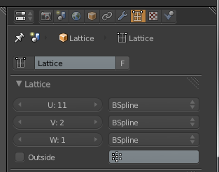
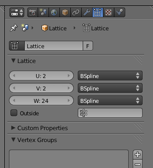
To set this up, on the Lattice change its settings to match the mesh, giving it a flat height, only two lengths but several widths for the deformation of the curling.

Next on the Paper, apply the Lattice Modifier and set the Object to the Lattice so that it can be affected by the Lattice.

Finally back on the Lattice, add a SimpleDeform Modifier, and set the type to Bend.  You'll notice that on first application, the Bend with neither be in the desired direction for curling, nor will it start the bend at the Empty.  This is where assigning the Empty to the Origin field and checking Relative will help.  Also turning the empty 90 degrees will turn the bend into the right direction.

At this point, all that's left is to Keyframe [I] the Deform>Factor by holding the mouse over the field and hitting [I], and you can create the following animation:


Saturday, March 17, 2012

ShrinkWrap Modifier

This entry will be covering use of the ShirnkWrap Modifier.  This modifier is most often used for adding clothes to a character, but it can be used whenever a mesh needs to conform to another mesh.

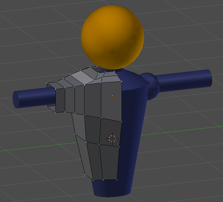
To demonstrate, I'll be using this simple body frame and giving it a shirt.

The first step to creating a shirt to use a ShrinkWrap is to make a rough mesh composition that mimics the general shape of the mesh to be conformed.  In this case, I simply started with a cube, and began extruding [E] and adding ring cuts [Ctrl + r].

You'll notice, that only half the shirt is shown.  Since the character is symmetrical, I'll be using a Mirror Modifier (with clipping) to ensure the shirt is also symmetrical.

An image of the full shirt with mirror enabled, that roughly follows the blue body.

Next we add the ShrinkWrap modifier to the shirt mesh.  Note that the field labeled Target represents the mesh to conform to.  Note also, that it is a single object, so if the body in this example was two meshes (which it was), they would need to be joined [Ctrl + J] first.  Or as an alternative, to keep them independent, a joined duplicate could be made just to create the shirt.

Finally, in the Offset field, this can be adjusted to scale the modified mesh outward (away from the body).

At first glance, the modifier does a somewhat poor job in that much of the blue body protrudes through the shirt, but this is simply because currently, our shirt mesh has so few vertices that the mesh can't conform to all the details of the body.  This works best for convex shapes, and more vertices would be needed to fill holes.

At this stage some manual manipulation is needed to ensure the body doesn't show through the shirt.  You may even find that you need to add more ring-cuts or extrusions to give enough detail to cover the body adequately.

Finally, a Subdivision Surface modifier can be applied to give the shirt a more smooth look.  More massaging of the mesh may be required.

Although there is some tweaking in the process, the ShrinkWrap modifier saves you a lot of time getting the general frame to match the body, than having to do the entire alignment manually.


Wednesday, February 29, 2012

Lattice Modifier

The Lattice Modifier is a unique kind of mesh deformation modifier, but with a special twist.  The modifier is not applied to the mesh, but affects the mesh as it interacts with the modifier.  The benefit of this is a non-permanent mesh deformation, which has some unique applications with animation.

So we'll start out first adding [Shift + A] a Lattice.

The resolution, or number of controllable vertices available in the lattice can be adjusted by increasing the U, V and W fields in the Lattice panel.

In Edit Mode for the Lattice, the vertices can be adjusted exactly the same way that meshes can be adjusted using the standard transformations.  In this example we'll be creating an hour-glass type shape using this lattice and a cylinder.

Now in adding the Cylinder, note that the cylinder needs many segments if the deformation is to be smooth and clean.  I used several ring cuts [Ctrl + R] in this cylinder and even add a Subsurf [Ctrl + 2] to keep the column smooth.  Note also, that although the cylinder doesn't have to be in the lattice for it to be effected, it must be along the primary axis (X,Y,Z) to be affected.

On the Cylinder object, add the Lattice modifier and for the Object, select the lattice we created earlier.

You will see right away that the cylinder is now deformed by the lattice and mimics its shape.  Although its less likely that you will use a lattice for this purpose, it serves a more practical purpose in animation.

In the example below, both the glass and the blue ball meshes have the same Lattice modifier, so you'll notice how the ball is affected by the lattice differently as it passes through, but in all cases it follows the shape of the lattice, delivering the illusion of a thick ball passing through a small hour-glass hole.

Monday, February 13, 2012

Weight Paint Displacement

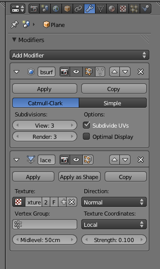
This entry goes over the process of weight painting or controlling the effect of a displacement modifier among a mesh.  So first we start out with a grid mesh, whose surface has been deformed via a displacement modifier seeded by a Cloud texture.


 Sub-Surf was also applied to improve the appearance.

A quick render of this will show the displacement is applied all over the mesh.  Now, if we want only some parts of the mesh to affected and others not, we can do this by defining a Vertex Group and applying weight painting.

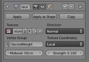
So first we define a vertex group.  The one I'm going to use here is SecondWeight.  The highlighted vertex group will be the one that receives the weight painting.

Switching over to weight-paint mode, we can now paint onto the mesh to apply the 'strength' of the modifier to different parts of the mesh.  Blue represents zero effect, and Red represents full effect.

From the pattern I've painted, the camera should see a long line of strong displacement a little to the right of the camera stretching toward the horizon, while there is less influence on the sides.

After painting is complete, set the Vertex Group in the Displacement modifier.

The effect of the weight paint (vertex group) should be apparent within the mesh even before rendering.

Rendering shows what we expect.  Strong displacement to the right of the camera, and softer displacement elsewhere.

Saturday, December 31, 2011

Decimate Modifier

The Decimate modifier is essentially a very simple form of polygon reduction.  For this example, I'll start off with an icosphere.

First I'll make something that needs to be reduced, I'll add a Subsurf modifier and apply it.  Now we have a sphere with way more vertices than is needed.

So now, I'll add a Decimate modifier, and not that you can control how much of the mesh is reduced by the Ratio slider, and the Face Count shows how many faces are now remaining in the mesh.

Note that you will only be able to observe the changes from the Ratio slider when in Object View [TAB].

The reduced mesh is shown to be almost the same as the original, though not as uniform.

Thursday, December 29, 2011

Ocean Sim

This entry will show how to apply the new Ocean Modifier in Blender 2.6.1

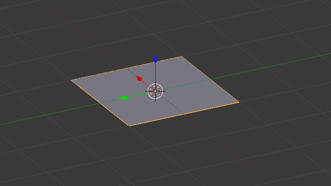
To start off, you need a simple plane.

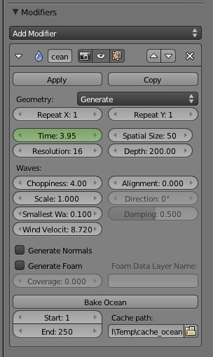
For that plane, add the Ocean modifier.

The plane will be scaled, and some default ocean deformation will be applied.

As a side not, if you want to animate the ocean, you can keyframe the Time attribute in the parameters.  For example.  Set the Time to zero and keyframe it at frame 1.  Then Set the time to say 10 secs, and keyframe that at frame 250.  When you play the animation [Alt+a], you can observe the ocean moving.

Otherwise, there are a host of other parameters that can be played with to modify how the waves will look, and how large the ocean is.

Once the ocean mesh is how you want it to look, choose the keyframe (in the animation) that is the desired wave pattern.

Next, add a Glass material to the mesh, and set the IOR to 1.33 (which is water).

Set your camera to a desired viewing position.

Next you need to add lighting to the scene to give it that out in the ocean look.  As an example, you can follow this entry Cylinder Lighting for the lighting below.

Since the original lighting is pretty drab, some simple compositing or post-processing in an image editor can give the image a little more life.

Wednesday, December 21, 2011

Cloth Simulator

The basic principle behind using the cloth simulator is to add a Cloth physics element (and modifier) to the cloth object, and add Collision physics element (and modifier) to the interacting objects.  In this demonstration, I'll show how a tent cover (sheet) can be draped over a metal frame. The frame is shown below.

For the frame (and also the ground) go to the Physics tab, and click on Collision.  No particular settings need to be adjusted here.

Now create a Grid object (which will be the sheet) and add a SubSurf modifier (to give more folding definition).  Now, the cloth objects Physics tab, click on Cloth.  For this one you do want to change some settings.  You can choose a preset material rather than trying to set all the different parameters.  And also, to make the collision realistic, you'll want to enable Self Collision.

Once the cloth (green) is in place, hovering above the frame, simply press [Alt+a] to run the animation, and the cloth will slowly float down onto the frame and wrap along it, influenced by gravity.

If you want the mesh at a specific folded frame, simply jump to that frame and apply all modifiers from top to bottom.  Applying the Cloth modifier will cause the mesh to be permanently deformed according to the simulation and can be used accordingly.

As well the animation of the falling cloth can be captured if that is desired.

Wednesday, December 14, 2011

Rotate Array

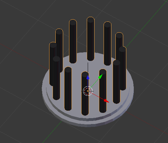
This tutorial shows how to array an object in a circular path.  In this example, we'll be rotating an array of the black columns around the round gray plate.

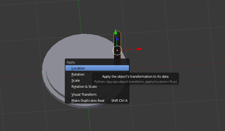
Move the black pillar into the desired position relative to the round plate, and be sure to apply all of its transforms (location, rotation and scale) using [Ctrl + a].

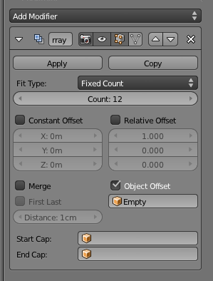
Next, apply the Array Modifier to the columns and make about 12.
Also, add and Empty object at the center of rotation (hence the center of the circle).

Next apply the following settings within the modifier.
Uncheck Relative Offset
Check Object Offset, and set it to the newly created Empty object.

Set the view to be orthogonal to the plane of rotation.  So this case was the z-axis looking down [NUM7].  Select the empty object, and rotate [r].  Note that the columns will now fan out into a perfect circle around the gray plate.

Final array'ed set of columns once fully rotated.