Wednesday, February 29, 2012

Lattice Modifier

The Lattice Modifier is a unique kind of mesh deformation modifier, but with a special twist.  The modifier is not applied to the mesh, but affects the mesh as it interacts with the modifier.  The benefit of this is a non-permanent mesh deformation, which has some unique applications with animation.

So we'll start out first adding [Shift + A] a Lattice.

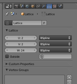
The resolution, or number of controllable vertices available in the lattice can be adjusted by increasing the U, V and W fields in the Lattice panel.

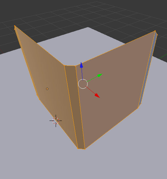
In Edit Mode for the Lattice, the vertices can be adjusted exactly the same way that meshes can be adjusted using the standard transformations.  In this example we'll be creating an hour-glass type shape using this lattice and a cylinder.

Now in adding the Cylinder, note that the cylinder needs many segments if the deformation is to be smooth and clean.  I used several ring cuts [Ctrl + R] in this cylinder and even add a Subsurf [Ctrl + 2] to keep the column smooth.  Note also, that although the cylinder doesn't have to be in the lattice for it to be effected, it must be along the primary axis (X,Y,Z) to be affected.

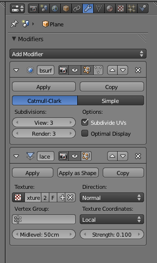
On the Cylinder object, add the Lattice modifier and for the Object, select the lattice we created earlier.

You will see right away that the cylinder is now deformed by the lattice and mimics its shape.  Although its less likely that you will use a lattice for this purpose, it serves a more practical purpose in animation.

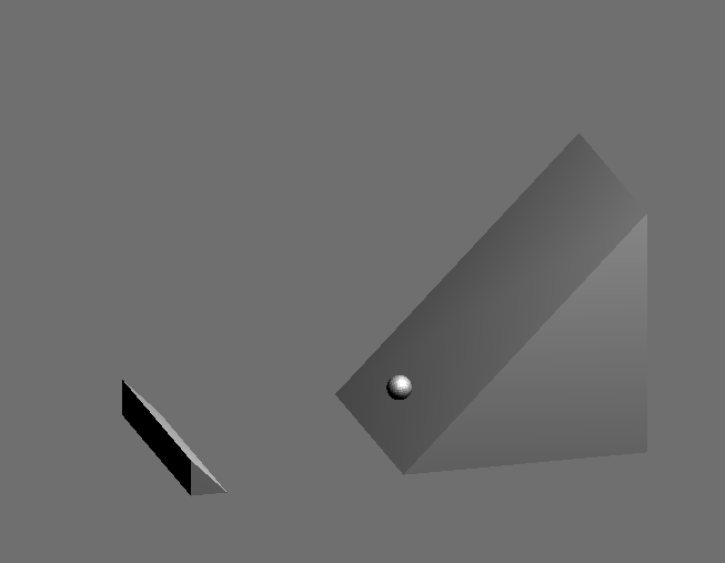
In the example below, both the glass and the blue ball meshes have the same Lattice modifier, so you'll notice how the ball is affected by the lattice differently as it passes through, but in all cases it follows the shape of the lattice, delivering the illusion of a thick ball passing through a small hour-glass hole.

Tuesday, February 28, 2012

Shape Keys

This entry will show how to apply Shape Keys.  This capability is most commonly applied to face manipulations to animate expression and talking for characters, but essentially it can be used whenever mesh deformation states make up the define the nature of the animation.  No rigging is necessary for this.

Note that shape keys can also be applied to Curves even though it isn't shown here.

So to start, we will use the monkey and animate its face using shape keys.

With the Monkey selected and in Object Mode, go to the Object/Mesh pallet, and in the Shape Keys section, click the plus button.  The first item displayed should be called Basis.  Click the plus button again, and this should create a second entry.  Select this entry, and now you can name this entry whatever you like, then move to the model.

In Edit Mode [TAB], you can now edit the mesh to capture this Shape Key state.  Note that since the normal shape is captured in the Basis key, anything done here will only be applied to the new key.  When you are done return to Object Mode [TAB].  Add as many Shape Keys as you like repeating this process.

To create shape key - keyframe, select the one of the shapekey elements in the pallete view and adjust the value (0 to 1.0) and press [i] and this will capture the value for that animation frame.

Next switch to the Animation View [Ctrl + LEFT].

Change the DopeSheet view to show the ShapeKey Editor.

In this view, you can animate between the Shape Keys by simply selecting a point on the timeline, and adjusting the scale amount (green numbered box) for each Shape Key.  In this way, you can combine Shape Keys and combine them in unique ways.

The final animation for this example can be viewed below:

Monday, February 27, 2012

Vert Distribution

This entry will show how to make use of the Vertex Distribution capability within Blender.  This a very useful effect when you need to have multiple instances (not copies) of an object arranged in a very specific order.

For this example, we'll see how to generate a circle of monkey's using only using to objects.  The first of the two objects is the Circle which will act as our instance reference.

Next we'll add a Monkey as our object to instance.

Next, parent the Monkey to the Circle either by dragging in the Outline panel (2.62) or [Ctrl + P].

Now, with the Circle selected, under the Object panel, select the Verts button in the Duplication panel.

This should create the view below in the scene.

To get a little more sophisticated and add more flexibility, we'll check the Rotation box (shown above).  Next select the original Monkey again.  Apply it's rotation [Ctrl + A].  Then on its Object panel, under Relations Extras, change the Axis shown below.

This should cause the Monkeys to look inward, as if they were all focusing on some important object.

Some other examples of meshes created using the VertDist method.  Note that each of these three objects were created only using 2 unique meshes.

Render Video

This entry takes from Blender Guru's quick tip on rendering videos.  For the full video click here:

This entry focuses just on compositing the rendered images into a quicktime video using the Video Sequencer in Blender.  So the first step assumes that the images have already been captured (doesn't have to be Blender images, can be any jpgs or pngs).

The first step is to switch to the Video Editor view [Ctrl + LEFT].


In this view, select Add then Image.

In the dialog box select all the images related to the video sequence [A] then select Add Image Strip.

At this point the image strip should be available in the timeline.  You may have to move the image sequence so that it starts at frame 1 or 0. Set the ending time of the animation to be the same as the last frame in the image sequence.

Now back in the standard view, you can adjust the animation render properties (as below) and render a new animation.  These settings will publish a quicktime .MOV.

Sunday, February 26, 2012

Game Engine Intro

This entry will introduce the mechanics of the game engine built into Blender.  We'll be creating a simple physics simulation of a sphere rolling down a ramp to exemplify this.  So we'll start off with the ramp and floor already modeled.

Switch the renderer to the Blender Game.

Next add a mesh sphere and scale it down to 0.1 or 10cm.  The precise scaling needs to be known for the purposes of manually setting the collider correctly.

In the Physics panel for the sphere set the following attributes to give the sphere a functional presence within the simulation (game).  Note that the radius of in this panel must match the size of the sphere, or the collider will be much larger than the object, and the collision interaction won't look correct.

Finally in the render panel, you can press Start to begin the game (or in this case simulation).

At this point, you should see the view change and the sphere should be affected by gravity and should roll down the ramp.
 You can press Esc at any time to cancel the game-running mode.

Once cool trick, is that if you enable Physics Visualization in the Display section of the Render panel, you can get extra information about your scene displayed while its running.

Tuesday, February 21, 2012

Material Viewport Color

This entry will explain a simple concept of material identification, as well as touching on a special surface in Cycles called the Holdout.

FOR CYCLES:
In the initial viewport we have 3 cubes that have different colors. However, these colors are not representative of what the render will look like.

In cycles, in the material panel, you'll notice a field called Viewport Color.  This is what the object will be colored when viewed in Solid render mode.  In this example, the red is obviously the cube in the middle. You'll notice however, that the actual shader or surface used is Holdout.

When we view the rendered image, we see three boxes with three unique materials, none of which are colored.  The 'blue' box has a Glossy shader, the 'red' has a Holdout, and the 'green' has the Emmisive shader.  It's worth noting that the Holdout shader is essentially the opposite of the emmissive shader.  As the emissive shader emits light, the holdout shader actually absorbs all light and reflects none.


Storing Materials

Typically Blender only saves materials that are associated with a mesh. 

This entry will show a quick way to save a material within a blend file without it being associated with any particular mesh.

In the material panel, the little F button means you want to 'fix' the material to the file even if it's not associated with a mesh.

Monday, February 20, 2012

UV Follow Quads

This entry will show how to use the UV unwrapping technique called Follow Active Quads.  This works particularly well with walls or beveled surfaces which have a continuous texture.  So for this example, we'll apply a brick texture to this beveled wall.


In Edit Mode [TAB], select all the vertices and bring up the UV Mapping menu [u] and select Follow Active Quads.

When switching over to the UV Edit mode [Ctrl + Left], you'll notice that the quads are now nicely and adjacently aligned in the view.

From here, add a new material to the mesh, and set the Color to an Image Texture.  Select the desired image texture, in this case a brick wall.  When you navigate back to the UV Edit view, you should see that texture available in the view for manipulating the vertices with respect to the image.

The final render for this example is three instances of the wall with the brick texture.


Quick Preview Render


When working in Render view in Cycles, sometimes the render takes too long and it's difficult to see how your changes are being effected.  Switching the Integrator to these settings will give a lower fidelity image, but a much faster render as you manipulate the scene.

Monday, February 13, 2012

Weight Paint Displacement

This entry goes over the process of weight painting or controlling the effect of a displacement modifier among a mesh.  So first we start out with a grid mesh, whose surface has been deformed via a displacement modifier seeded by a Cloud texture.


 Sub-Surf was also applied to improve the appearance.

A quick render of this will show the displacement is applied all over the mesh.  Now, if we want only some parts of the mesh to affected and others not, we can do this by defining a Vertex Group and applying weight painting.

So first we define a vertex group.  The one I'm going to use here is SecondWeight.  The highlighted vertex group will be the one that receives the weight painting.

Switching over to weight-paint mode, we can now paint onto the mesh to apply the 'strength' of the modifier to different parts of the mesh.  Blue represents zero effect, and Red represents full effect.

From the pattern I've painted, the camera should see a long line of strong displacement a little to the right of the camera stretching toward the horizon, while there is less influence on the sides.

After painting is complete, set the Vertex Group in the Displacement modifier.

The effect of the weight paint (vertex group) should be apparent within the mesh even before rendering.

Rendering shows what we expect.  Strong displacement to the right of the camera, and softer displacement elsewhere.