Wednesday, May 9, 2012

Edge Functions

This entry will cover most of the functions defined in the Edge menu which can be brought up in Edit Mode, with the [CTRL + E].

Edge Loops
The first and most important edge tool is the adding edge loops [CTRL + R].  This is the primary method of adding vertex detail while maintaining quads in your topology.

An edge loop can also easily be selected by [ALT + RightClick] an edge in the loop.

An edge loop can be easily deleted by selecting the loop and pressing [X] then selecting Delete Edge Loop.

An edge lop can be easily moved along its edges using the Edge Slide function.

Edge Creases
When using the Subsurf Modifier, it is common to use extra ring-loops to tighten up the corners.  A better method which does not require more vertices is to select the edges desired to be tightened and to adjust the Mean Crease found in the properties bar [N].  This is the same function as the Edge Crease in the edge menu.  Mean creased edges are identifiable on the mesh with a magenta color.

Marking Seams
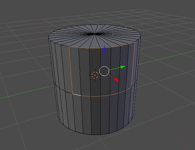
The function of marking seams in your mesh is to isolate particular faces for UV unwrapping.  In the example
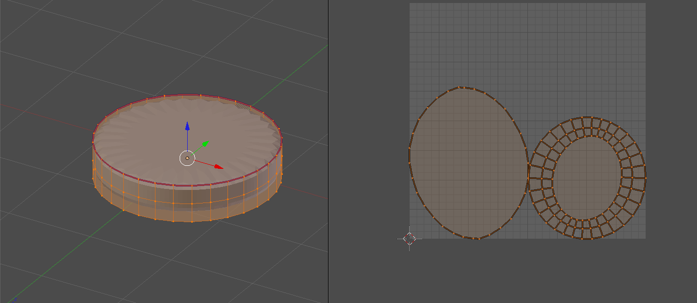
I marked the top circular edge of the cylinder, so that when I UV unwrapped it, it's its own island in the UV map.  UV marks are highlighted as magenta colored edges (which is ambiguous with the mean creased edges).



Marking Sharps
The function of marking sharps is the same as marking seams, except that the purpose for marking sharps is to give you more control of a smooth shaded surface.  For example, this simple extruded box shape is smooth shaded, and has the typical weird shadowing (as would be expected).
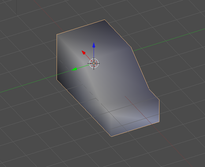
This weird shading can be mitigated by applying an Edge Split Modifier, which essentially, breaks apart the faces so they are separate (meaning duplicated vertices), so the vertex-normal-interpolation that is performed is isolate to the normal of the face to which it is attached (still with me?).  Empirically, this just makes all the edges sharp again (and the faces look flat).

The modifier gives you some control in the form of the Split Angle, but in some cases that is not enough control.  In some cases you may want to specify which edges/faces exactly that you want excluded from the rest of the smooth calculation.

This is where Mark Sharp comes in.  It works in tandem with the Edge Split Modifier.  For all faces (or set of edges creating faces) selected, when you apply Mark Sharp, the Edge Split modifier automatically assumes it to be split rather than relying on the split angle test for the edge.

In this example I marked the sides as sharp, so the side faces now look nice and crisp and flat, and the top faces are still smoothed together.
This same function can be achieved without the Edge Split Modifier by simply selecting the faces and choosing Edge Split in the edge menu.

Bevel (Reference)
Info on this can be found here: Bevel

Bridge Two Edge Loops (Reference)
Info on this can be found here: Bridge

Monday, May 7, 2012

Animation Blur

This entry covers the function of adding blur to animations.  This can be done by enabling the Sampled Motion Blur box in the Render tab.  There are two parameters that can be adjusted, Motion Samples increases the fidelity of the blur, while Shutter determines the length of the streak as it pertains to a camera shutter speed.

The use of this can add realism to your movie as most cinema is not recorded in high-speed shutter, so some blur occurs.  A comparison of a single frame of no blur versus blur shows the obvious difference, though in motion it's subtle.  The first image shows a transition of words without blur.

This image shows the same exact motion but with blur turned on.

The full video without blur:

The full video with blur:

Sunday, May 6, 2012

BMesh Introduction

BMesh is the overhaul of the mesh system within Blender that was first introduced to the software with version 2.63.  There is a host of features that have been added to the mesh system, mostly which center around the new NGON (polygons with verts greater than 4) capability.  The image below shows an example of an NGON extruded from the cube with 8 vertices.  

This entry is based on a tutorial which can be found here: Blender Cookie Tutorial


Next I'll walk through the main new features related to NGON manipulation. The first is 'filling' two vertices with an edge that splits the NGON.  This is done by selecting the vertices and hitting [J].  Hitting [F] instead will draw a line on top of the NGON instead of splitting it, which in almost all cases is undesirable.
Note that a ring loop of more than 4 vertices can be filled using [F] to create an NGON.

The next feature is the Merge or Dissolve feature.  This will essentially take the selected objects (verts, edges or faces) an dissolve them, but potentially to create an NGON.  The example below shows 4 faces being dissolved to make an NGON.  The dissolve can be performed in the delete menu [X].

Another feature in the delete menu [X] is the Edge Collapse.  This will take the selected edge(s), and collapse it's adjoining vertices to a central point.  This can be seen on a single edge in the image below.

The final delete capability is the Limited Dissolve.  Although it intuitively should be in the delete menu, I could only find it through the generic search [SPACEBAR] and typing in the name.  This basically deletes all the edges between the vertices.

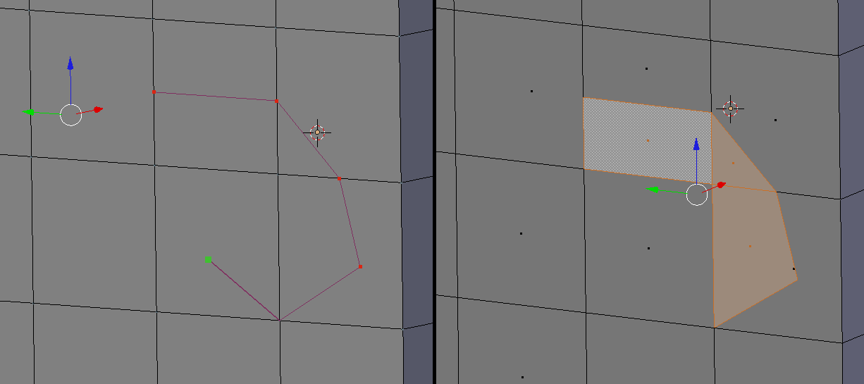
The final new feature is the updated knife tool.  This can be initiated with the [K] key.  In this mode, the cursor marker becomes green, and you can essentially draw a path of cutting new geometry.  You must hit [ENTER] when the drawing is done to keep the drawn path.  This is probably the surgical method for subdividing NGONs since you can't use [w] subdivide across them.

The example below shows how drawing a path with the knife tool creates new face geometry.  Note one trick that if you hold [CTRL] while drawing, the marker will snap to vertices or the midpoint along an edge.

Final thoughts, NGONs are useful for making the workflow of mesh modeling easier, but for most cases with gaming or low-poly models, you'll want your entire model to be only quads (and possibly if absolutely necessary, triangles).

Another warning to note, NGONs behind the scenes may be made up of triangles.  You'll observe this if you try to subsurf an NGON.

Saturday, May 5, 2012

Section View

This short entry shows a simple utility for viewing your mesh, which is the section view (or cutaway view).  To enable this view enter [ALT + B].  This produces an action similar to the box select [CTRL + B], except, what you select will maintain in the view, and everything else will be hidden.

In this example, I selected the right half of suzanne from the top view.

You'll notice that when viewing the mesh from the side, you can now see inside since the left side is hidden.  The section view can be turned off by pressing [ALT + B] again.

Face Projection Snap

This entry covers the capability of snapping a mesh geometry to another, similar to the shrink wrap modifier effect, but projected from your present view.  We'll view this effect with a simple example of projecting a grid to a cylinder. 

To start out, create a cylinder and a grid.  I colored the grid blue to make it easier to see (after the snap) and I scaled [S] it smaller to allow it to fit more easily onto the cylinder.

While in edit mode, with grid selected, set the snap parameters in the bottom toolbar as shown below.  The Snap Element should be set to Face, and the Project button button should be enabled.

Next, move your view (not the camera) to where you want to project.  The mesh will be projected essentially from your view, down your line of site (-z axis) toward the mesh, and will deform the mesh according to the mesh it hits.  In this example, I just did the side view [NUM 3].

To snap, with all vertices selected [A], press [G], then [Ctrl].  Once you click or hit enter it will activate the snap.  If you right-click it will reset.

The snap won't be obvious at first until you change your view.  Upon inspection you'll notice that the grid is now nicely wrapped around the cylinder.  Because this is done very closely, the grid may not cleanly rest on the cylinder, some parts may protrude into the cylinder. I moved the grid slightly away from the cylinder to give it a cleaner look.

The final render with the grid slightly extruded [E] away from the cylinder.


Saturday, April 14, 2012

Mesh Modeling Best Practices

This entry aims to summarize some of the commonly-agreed-upon best practices in regards to mesh modeling.  The approach of applying intelligence in the design of a mesh is sometime referred to as optimizing the Mesh Topology.  To say that a mesh is optimized begs of the question of what it's optimized for.  In this case, it's all the big applications of 3D modeling: animation, mesh smoothing, and gaming engine import.

The first topic to discuss in mesh topology is the approach to modeling.  The two primary methods are Box Modeling and Polygon Modeling.  In box modeling, the modeler starts with a mesh primitive (i.e cube, cylinder or a sphere) and extrudes faces and adds ring cuts and tweaks the mesh until it suits its purpose.  


With Polygon Modeling, the modeler works primarily with edges and vertices, to make its creation.  This method is much more arduous and intensive, but provides the highest level of control, and allows for much more sophisticated (but efficient) mesh topologies to be created.  This is the preferred method for organic shaped models.

In either case, there is one paramount rule that seems to be expressed in many forums, even though there are few exceptions.  This rule is that a modeler should avoid using triangles at all costs.  There will be exceptions, but quads should be used whenever possible.

Triangles are a nuisance to subsurfacing, to animation, and to creating efficient meshes that are imported into gaming engines.  In the case of subsurfing, you are dividing the polygon into smaller pieces, and dividing a 4 by 2 is obviously a cleaner arithmetic than dividing 3 by 2.  Using triangles results in unpredictable, or pinched geometry both in subsurfing and in animation.  This can easily be seen when a cylinder (with triangles for the capped ends) is subsurfed.  In the image below, the ridges at the top are caused by the triangles.

Although the triangles could be removed through some strategic selecting and converting of Tris to Quads [Ctrl + J], a simpler approach which renders the triangles less involved in the subsurf would be to start with uncapped ends, and extrude [E] and scale [S] the top ring to create a ring of quads first, then extruding [E] the ring again, and collapsing [W merge] the final hole.  This will make the tesselation between the sides and the top about quads (not tris), and hence the curve will be smooth.  The image below shows the difference between the Quads vs Tris approach.

Another example of a primitive that naturally has triangles is the UV Sphere.  The image below highlights the ring of triangles similar to the cylinder example.  However, there is an easier way to create a sphere without triangles.  Start with a cube, select all vertices, and subdivide [W] it a few times.  Then, sphereize [Shift + Alt + S] the cube, and you'll get the sphere on the right, with all Quads, but some Poles (which we'll discuss next).

The simplest definition of a Pole is a vertex that does not connect to four edges.  Except for cases like the sphere/cylinder, a pole in a quad mesh will have either 3 or 5 vertices.  The image below shows an example of a situation where there is a 5 edge pole, and a 3 edge pole.

Note in zoomed out image of this example, the unique effect on edge-loops that occurs.  The red set of faces in the mesh represents an edge-loop which is shaped like an 'O'.  But notice in the highlighted faces, that edge-loops running up and down and left and right, essentially bypass the red ring.  This is the nature of poles and how they allow more complex topologies while maintaining an all-quads mesh.

In conclusion, use the two different modeling methods, Box or Polygon based on the needs of the model.  But in any case, always avoid triangles, and use poles to help solve complex mesh situations to maintain an all quads topology.

A great quick video on manipulating mesh topology can be found here: Blender Cookie Tutorial

Friday, April 6, 2012

Transparent Decal

This entry will cover a simple approach to applying an image (PNG) with transparency to a material that has color.  The image with transparency is the eyes seen below.


We'll be applying these eyes to a segment of the cylinder, and we've isolated the segment by highlighting the surrounding edges as shown below.

These edges will be made into a Seam so that we can find them in the unwrapped map easier.  This can be done with [Ctrl + E], and selecting Mark Seam.  Note that breaking the mesh into UV islands is not recommended for models to be used in real-time (gaming) applications.

Once the vertices are marked and the mesh is unwrapped using the standard [U] and Unwrap, moving over to the UV/Editor [Ctrl + LEFT], should show a UV map similar to the one below.  Our seams are now very obvious to find.

Since we only want the image to display in our segment, we'll enlarge it accordingly and move all the other elements of the mesh outside of the image.

Back in the standard view, create a new material for the cylinder, and add a new texture.  In the texture properties, all you need to do is set the Extension to Clip, and ensure the Coordinates are UV and the Projection is Flat.  No further fiddling with transparency is needed. The transparency is covered automatically.

The final render with the eyes textured onto the cylinder.