Monday, February 20, 2012

UV Follow Quads

This entry will show how to use the UV unwrapping technique called Follow Active Quads.  This works particularly well with walls or beveled surfaces which have a continuous texture.  So for this example, we'll apply a brick texture to this beveled wall.
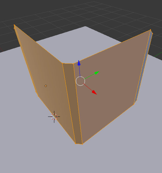

In Edit Mode [TAB], select all the vertices and bring up the UV Mapping menu [u] and select Follow Active Quads.

When switching over to the UV Edit mode [Ctrl + Left], you'll notice that the quads are now nicely and adjacently aligned in the view.

From here, add a new material to the mesh, and set the Color to an Image Texture.  Select the desired image texture, in this case a brick wall.  When you navigate back to the UV Edit view, you should see that texture available in the view for manipulating the vertices with respect to the image.

The final render for this example is three instances of the wall with the brick texture.


Quick Preview Render


When working in Render view in Cycles, sometimes the render takes too long and it's difficult to see how your changes are being effected.  Switching the Integrator to these settings will give a lower fidelity image, but a much faster render as you manipulate the scene.

Monday, February 13, 2012

Weight Paint Displacement

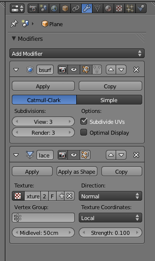
This entry goes over the process of weight painting or controlling the effect of a displacement modifier among a mesh.  So first we start out with a grid mesh, whose surface has been deformed via a displacement modifier seeded by a Cloud texture.


 Sub-Surf was also applied to improve the appearance.

A quick render of this will show the displacement is applied all over the mesh.  Now, if we want only some parts of the mesh to affected and others not, we can do this by defining a Vertex Group and applying weight painting.

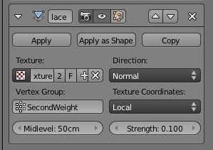
So first we define a vertex group.  The one I'm going to use here is SecondWeight.  The highlighted vertex group will be the one that receives the weight painting.

Switching over to weight-paint mode, we can now paint onto the mesh to apply the 'strength' of the modifier to different parts of the mesh.  Blue represents zero effect, and Red represents full effect.

From the pattern I've painted, the camera should see a long line of strong displacement a little to the right of the camera stretching toward the horizon, while there is less influence on the sides.

After painting is complete, set the Vertex Group in the Displacement modifier.

The effect of the weight paint (vertex group) should be apparent within the mesh even before rendering.

Rendering shows what we expect.  Strong displacement to the right of the camera, and softer displacement elsewhere.

Sunday, February 12, 2012

Alpha Texture - Internal

For the Cycles version of this, go here: Alpha-Texturing in Cycles

This entry will walk through the process of creating an alpha-texture in with the Blender internal renderer.

The scene starts out with a plane (gray) which will contain the image (with transparency), and a background plane which is simply blue.

The image with transparency is shown below, which is simply the blender logo in PNG form.

The first step of creating an alpha-texture is to set the following transparency properties in the material.

Next set the following parameters in the texture.  It is in this texture that you assign the image containing the transparency.

[UPDATE 6/120/14]:  You may also need to check the Use Alpha box in newer versions of Blender.


[OPTIONAL] Finally, the material(s) receiving the shadow needs to have these parameters check also for the light to pass through the transparent parts of the texture.

 The final render of the logo floating over the blue plane.

Alpha Texturing - Cycles

This entry will walk through the process of applying an alpha texture such that the lighting in the scene reacts to the transparency.  This tutorial is specific to the Cycles renderer, for the Blender Internal approach, go here: Alpha-Texture Internal

Our starting scene just has two planes, one with the image (containing transparency) and the second acting as the background.

The compositing view for the material is shown below.  Note that there are two image textures.  I'll describe the two images that are needed next.

Our original image which connects to the Diffuse BSDF is the original image with transparency.  This was simply a PNG of the blender logo.

The second image that flows into the Transparency BSDF node, must be a grayscale image representing the alpha channel.  Black is opaque and white is transparent (with gray being in between values of transparency).  This image must be generated in an image editor and imported separately.

The final rendered result shows the transparent plane hovering over the background.  Note how the light respects the transparency and the shadow matches the shape of the image rather than the rectangular plane that it is resident on.

Saturday, February 11, 2012

Texture Stencil

For the Cycles Renderer version of this, go here: Texture Masking - Cycles

The first part of creating a stencil or texture mask is to create the mask image.  This is commonly done with a grayscale image.  In our example, it will be a simple black and white image drawn in Blender.

To create a simple mask, select the object, in our case, the Plane, and switch to Edit Mode [TAB].  The easiest way to unwrap a plane for UV mapping is to get to an orthogonal view (in my case from top view [NUM7]) and unwrap the plane using the Project from View.

In the UV Editor window, simply create a new image which will default to a black background.

Now with this new image mapped, switch back over to the 3D Viewport, and change the mode to TexturePaint.  In this mode, you can paint directly on the mesh using the Tools [T] pallet.

I painted a simple swirl with a white brush.
Back in the UV Editor window, make sure to save the image.

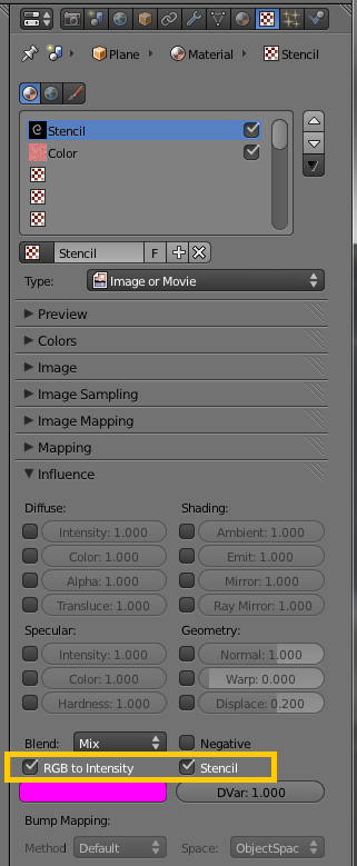
Now on the object (our plane), create a new material and a new Texture.  Note that two textures will be required, one for the mask (stencil) and one for the underlying image.  For the stencil texture which will act as the mask, the two main fields to check are RGB to Intensity and Stencil.  This will essentially turn the image into a mask, where white passes the next texture through, and black blocks.

For the underlying texture, the settings aren't important, but I simply made a red noisy texture from the internal Clouds image.

 The final render shows the red coming through the mask, on top of the base white material.

Specular Texture

This entry will walk through setting a material with a specular texture.  This is most often useful when creating a material where the surface has either very complex specularity such as scratched metal, rough surfaces, or in this case snow.

Below is the starting mountain scene which we will give a snow-like material.

 
The two lights will be explained a little later.

For the landscape object, create a new material, and set its Specular Intensity to 0.  This will prevent the material specularity from overriding or overpowering the texture specularity.  The Hardness however, will still be used to control the level of spread of the specularity among the material.

Next create a new texture.  In this case, I used the Clouds texture built in and set the following parameters.

Then, under Influence, enable the Specular Intensity, and adjust its value for strength of the reflection.

Since we are using the Blender internal renderer for this example, to get the specular texture to show correctly, a second light is needed to focus just on the specularity of the texture.  Hence the second light is setup to only affect Specular (Diffuse has been unchecked).

This results in the following render, where you can see the white material, now has some shiny noise on it, indicative of the noise specularity of snow.