Thursday, May 31, 2012

Quick Mesh Mirror

This is a quick tip on how to mirror a mesh very easily.  Sometimes mirroring is needed with meshes, and a rotation won't suffice.  In this case, I have the left half of suzannes face, but suppose I need the right side.  I could use a Mirror Modifier, and then apply and delete the old half, but a simpler and cleaner method is to Scale to -1.  

You can even use this method with restricted axis.  So I simply Scaled [S], restricted to the x-axis [X], and entered -1.  This produced a perfect mirror of the mesh while maintaining the original mesh origin.  No deleting necessary.

Object Transforms

This entry is a summary of the object level transform functions.

To perform standard operations on a mesh in the Object Mode.

[G] to translate
[R] to rotate
[S] to scale

All of these can be restricted to the standard Cartesian Axis with [X], [Y] and [Z] respectively.

Specific values can be entered for more precise deltas.

Conversely dual axis changes can be applied with [SHIFT+X], [SHIFT+Y] and [SHIFT+Z]. Where the axis selected is the one that is omitted from the transform.

All transform changes can be viewed in the properties panel [N].
In this panel specific values can be set, or values can be Locked.

All transforms can be reset:

[ALT+G] to reset translate
[ALT+R] to reset rotation
[ALT+S] to reset scale

All transforms can be applied (keep but reset references) with: [CTRL+A]

Outliner

This is a quick entry on some features of the Outliner--the view that displays the hierarchy of the objects in the scene.  The first concept is the visibility filter.  The combo box at the bottom which defaults to All Scenes, can be changed to any of the different filtering views.  

One that would be very helpful would be to set Visible Layers which helps make the Outliner more relevant if moving irrelevant (but needed) objects to other layers.

The next feature which is relatively new (probably 2.6) is the ability to drag and drop objects in the Outliner to achieve parenting.  The icons must be grabbed for this to work, not the name.  As well parenting can also be achieved with [CTRL+P] with the parent object being selected last.

Finally, it's worth mentioning the three icons on the right of every listed object.  These icons toggle visiblity in the scene (eye), selectability (arrow), and visibility in render (camera) respectively.

Friday, May 25, 2012

Specular Texture

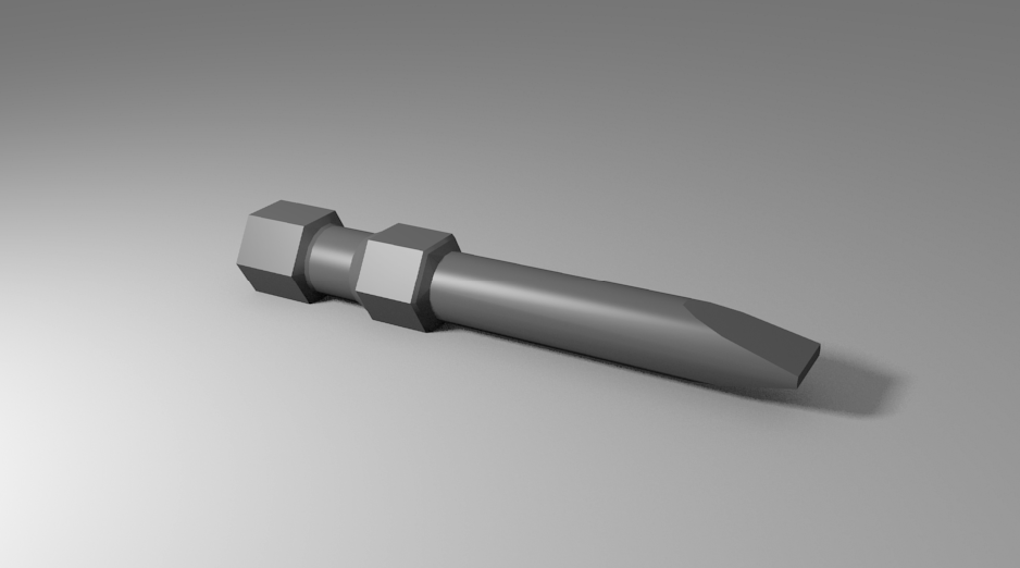
This entry covers the topic of Specular Textures.  Essentially it is applying a grayscale texture as a specular map, to give an object a non-uniform specularity.  To demonstrate, I have a model of a hex bit that has a single material that is a solid gray with the standard uniform specularity.  I'll be adding a stretched cloud texture to give the bit a more brushed metal look.


The first step is to remove the material specularity.  This can be done by dropping the Intensity to 0.  The Hardness should me maintained however, or possibly increased.

Next create a new texture for this material.  Regardless of what you use for the texture, be it an image or a built-in Blender texture, essentially the main parameters to change are in the Influence section.  Uncheck the Color in Diffuse and check the Intensity in the Specular.  Now the light values of the texture will provide high specularity while the dark parts will provide less.

From here, the nature of the specularity is up to your creativity.  I used the following settings with the built-in cloud texture to produce the brushed metal look in the final render below.

Final render with the specular map applied.  The metal almost seems to have a normal map feel, but it's purely just specular map reflection.

Monday, May 21, 2012

Alternate Input

This entry covers some quick tips about using Blender in the less than ideal configuration.

So the ideal configuration is using a 2-button mouse with a scroll wheel, and as well as a keyboard with a dedicated number pad or NUMPAD.

There are many scenarios where this ideal configuration isn't available (i.e. ergo mice, laptop, track pad, mac etc).  So here are some quick tips for working with these configurations:

If you have a middle mouse button, and therefore can't middle click, you can emulate the 3rd button by checking the Emulate 3 Button Mouse in the User Preferences window under the Input tab.  What this does is allow you to [ALT+LEFT-CLICK] to perform a middle mouse click.

In the same window, to mitigate a keyboard that has no dedicated numpad, you can also Emulate Numpad by checking that respective box.  What this will do is override your regular number keys which would normally control your layers, and apply the NUMPAD views instead.

There are two scenarios where having a scroll wheel is very handy.  One is adjusting how many ring-loops are applied when you [CTRL+R] to insert an edge loop.  Changing the number of rings can also be achieved by [PAGE UP] and [PAGE DOWN].

This is the same as the ring loops, when working with Proportional Editing [O], Paint Select [C] or any tool that has a radius control, you would normally use the scroll wheel to adjust the size of affect.  You can also use the [PAGE UP] and [PAGE DOWN] here as well.

Note that there are known issues with Logitech Mice not functioning correctly upon first connection.  In these cases, open the Logitech driver/software, and set the Scroll Wheel button to be either Middle Button or Middle Click instead of its standard Zoom or AutoScroll.

Sunday, May 20, 2012

Texture Atlas


This entry will cover a very important technique for providing improved texture detail on meshes for gaming purposes while minimizing the number of materials needed.  In gaming it is very important to have as few materials as possible, as every unique material in a mesh requires a separate 'Draw Call'.  So if possible you want to combine your materials into one single map (or Texture Atlas).  

In our example I've started with a sphere that has been UV unwrapped via a seam [CTRL+E] around the equator. 
I applied two different materials, one a brick image and one a rug image.  So to begin, we have a single mesh wit two materials, each with their own image texture UV mapped onto the sphere.  The goal is to combine these two materials into one.

To combine the two, we will essentially be baking the rendered textures onto a new UV map on the sphere. So on the mesh tab, press the [+] button on the UV Maps panel, and name the new map.  In this image I named it 'BakedUVs' but later I'll refer to it as just 'Baked'.

Note: For the baking to work be sure that the new UV map 'BakedUVs' is selected.

At this point, go to the UV Editor [CTRL+LEFT] view, you can view the UV unwrapping for this new UV map.  You can change it, but I've had the most success just leaving it the same as the original.  However, you do need to create a new image.  This should appear as a black square behind your map.

Also note that the mesh must be selected (highlighted orange) while in this view (as shown below).


Next is the baking, but before you move onto this step, in the case of a sphere, to make the texture looking cleaner and smoother, I applied a subsurf and smooth shading to it.  The baked textured will be based on the render, so any of these features will be applied by the bake.

Go to the Render Tab, and at the very bottom you'll find the Bake section.  You don't need to change any parameters just hit Bake.


If you return to the UV Editor window you should now be able to see your new texture baked onto the new image.  This now has both materials on one texture, and the lighting from the rendered scene can now be seen (most obviously on the brick side of the texture).  

Note: Make sure to save this new image.


The following steps will simply show how to reduce your materials down to one to be transferred into a gaming engine such as Unity.  You may want to save as a different filename to preserve the original two-materials in case you want to change it and re-bake.

The first step is to remove the other (original) UV map and just keep the new baked UV map.

The next step is to create a new single material, so the other two can now be removed.

Finally, on the new material, add a new texture and assign the new Texture Atlas which was created from the bake, and make sure the new UV Map is selected.

 Now when rendered, you have both textures/materials applied while using only one material.

The ultimate benefit now is if you export the file to an FBX and transfer the model with its texture into Unity, you can get the same texture detail, now with one UV map and one material.  Note in the stats window that the draw call is only 1.

Friday, May 18, 2012

Camera Track Object

This entry is just a simple demonstration of enabling camera tracking on an object.  This is not the camera tracking related to video footage, but forcing the in scene camera to point at an object in your scene.

This video shows a quick demo of it.  To enable the feature, select the Camera first, then select the target object.  Then enter [CTRL+T], and select Damped Track Constraint.  At this point, if you move the camera with [G], the camera will always point at the selected object.  

Also, note that if you rotate [R], the camera will always rotate according to the vector of the camera.  This feature is very similar to the idea of a Quaternion.