Thursday, March 22, 2012

Loop Tools - Bridge

Update Version 2.63
The capability of edge loop connecting is now built-in to Blender in version 2.63.  The feature can be accessed through the specials menu [W] and select Bridge Two Edge Loops.  The approach is the same before, however the built-in one doesn't have the fancy features of twisting and adding segments.


Older than Version 2.63
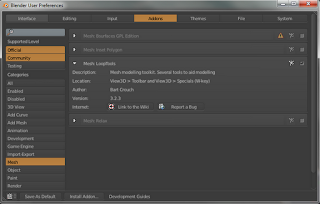
This entry covers a vast Add-On called Loop Tools, and specifically the Bridge capability..  This has been built-in for quite a few versions now and so can easily be enabled in the User Preferences > Addons.  There are very many mesh tools in this Add-On, but we'll be focusing on the Bridge capability for this entry.


For this example we have a set of curved pipes created using some curves and a Mirror Modifier.  It is worth nothing that the holes are perfectly aligned with each other due to the mirror, and now we'd like to connect them, but not have to select individual vertex pairs and fill [F].

A much faster and cleaner method is to select the two rings to be connected and use the Bridge tool.

Looking at the parameters in the Tools [T] menu, there are a number of settings that can be applied.

The simplest approach in this case is to connect the two loops with a single segment, by setting the parameters and clicking the Bridge button.

Further examples show setting 10 segments to give the mesh more definition (potentially for further manipulation).

Apparently you can also apply a Twist to the bridge giving way to a twisted mesh for a handle.

The Grease Pencil

The Grease Pencil is a very simple tool in Blender that has many useful applications.  In its simplest form, it just provides the ability to draw in the 3D View.  However, this can be useful for explaining, storyboarding, quick animating, etc.  

We'll go through some of the features and some of these applications.

The Grease Pencil is always available in the Tools [T] menu on the left side of the 3D View.  To begin drawing at any point, any of the four modes: Draw, Line, Poly and Erase can be selected.  This will allow you to make one stroke.  If Use Sketching Session is selected, then a new layer will be created and you can make many strokes.

The commands for these modes are:

  • Draw: D + LMB
  • Line: Ctrl + D + LMB
  • Poly: Ctrl + D + RMB
  • Erase: D + RMB
  • Exit: Esc


In the Properties Panel [N], to the right of the 3D View, are more parameters that can be adjusted.  When you select Use Sketching Session, a new layer is created.  In this case, it is called GP_Layer by default.

In the panel above, note that there are four different Drawing Settings.  These each affect the scene differently as will be shown below.  Four different marks were made, each with a different drawing setting.

Note that when the scene is moved, their characteristics are revealed.

  • Cursor/Stroke:  Draws within the scene, but not on meshes.
  • Surface:  Projected onto mesh in the scene (does not move with mesh though)
  • View:  Static in the 3D view

Note that X-Ray is turned off so that's why you can't see the lines through the mesh.

Finally, another common method for employing the Grease Pencil is to sketch out a simple animation.  The drawings created are all tied to specific frames.  So each frame can have its own drawing.  These can be animated if the timeline is played.  As well, to facilitate animating, the Onion Skinning option is available in the Properties Panel, which, as shown below, allows you to see lighter traces of the previous frames (also designated in the panel).

Tuesday, March 20, 2012

Baking Normals

This entry will be covering the concept of Normal Baking.  This is very useful for adding very high detail to very simple geometry.  This is very important for applications such as gaming where high detail, but low polygons are required. This example will take the simplest approach to Normal Baking, and that's simply adding texture to a plane.

So first off, the detail is created with an actual mesh.  in this case, I created a simple raised edge surface, which is the same size as the regular plane below it.

The blank plane below is the target object which will receive the map baking.  The normal map will need to be projected onto the UV map, so the receiving plane needs to be unwrapped [U].

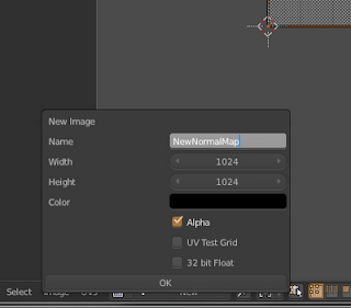
In the UV Editor View, create a new image and name it something appropriate relating to normal maps.

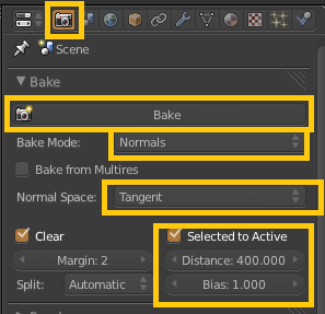
Next is baking, but before this is done.  Back in the 3D View, make sure to select the detailed mesh and the blank receiving mesh, in that order.  Then in the Render palette, set the following parameters in the Bake section.  Note: The values defined here were specified in a CG Cookie Tutorial i saw.

When you finally click Bake, back in the UV Edit View, you should now see the the normal map created as an image on the receiving plane.  Save this image somewhere on your harddrive.

Next we'll apply that normal map to the receiving plane so that it is visible.
Follow the next sequence of parameter settings for the Texture of the plane, as would be standard applied.


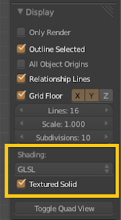
Finally, to be able to see the texture in action in the 3D View, set the View Mode to Texture, and in the Properties Panel [N], set the following Shading settings.


Now in the 3D view, you should be able to see the new normal map in all its gory.  It will update in real-time as you move and change the lighting of the scene.  And as was originally stated, all this detail is simply a normal map on a single plane (quad).
Monday, March 19, 2012

Stretch To

This entry covers an obscure but useful rigging feature known as Stretch To.  This method basically helps fix ugly 'pinching' at joints where bones are bending (i.e. elbows).

To demonstrate this, we'll use a cylinder with many ring-cuts [Ctrl + R] as our arm which we will bend.

Right off, just applying a simple bone setup shows a great deal of pinching at the point of rotation.  We'll be using a Stretch To bone to alleviate this.

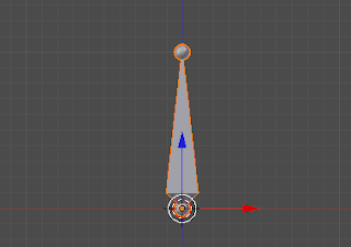
First, with the Armature selected in Edit Mode [TAB], move the cursor to the 'forearm' of the armature and add a new bone [Shift + A].

Select the new bone, then Shift select the 'forearm'.  Then connect the bone [Ctrl + P] as detached, so choose Keep Offset.

Rotate the new bone so that it intersects the top of the lower 'bicep arm' bone.  Move the cursor to the tail of the new bones position [Shift + S].

Now select the 'bicep' bone and then Shift select the new bone.  Use the Constraint command [Ctrl + Shift + C] to bring up the constraints menu and select Stretch To.

At this point the new bone should now move in such a way as to maintain its position tethered between the two bones.

Adjust the Head/Tail value and the Influence to get the tail of the new stretch bone to line up with the cursor once the arm is bent.

Finally, move to Weight Paint mode [Ctrl + TAB], and select the new stretch bone.  Paint its influence onto the mesh till the desired pinch attenuation is achieved.

Compare the original (left) with pinching, to the stretch bone approach (right).  The difference is subtle, but the stretch to approach is more natural, especially for joints such as these.

Inverse Kinematics

This entry discusses the rigging feature known as Inverse Kinematics (IK).  In Blender this is available when in Pose Mode, and can be found in the Tools [T] menu (as shown below).

When this is enabled, essentially, parent bones will automatically adjust to the movements of the most child bone.  In the image below, the lowest bone is being translated, and the parent bones are being bent accordingly.  Conversely, without Auto IK, you would have to rotated and translate each bone separately working from the parent down to the child.

The general rule for when to apply IK or not, is for limbs that bear weight or support the rest of the armature, IK should be used, for everything else use Forward Kinematics.

Sunday, March 18, 2012

Rig X-Mirror

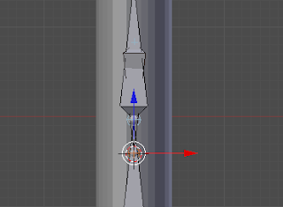
This entry covers the use of the X-Mirror option when rigging bones.  To start this short tutorial, start we'll start with a simple bone.

With that bone selected and in Edit Mode [TAB], the following option is available in the Tools [T] menu.  Check this box to enable X-Axis Mirroring.

What this does is allows you to create a mirrored bone structure when viewing orthogonal to the X-Axis or [NUM1].  In this case however, to make use of the mirror you must extrude with [Shift + E] rather than just [E].  This tells Blender to make use of the mirror option.

From here, all bones extruded [E] from the mirror extrusion will also be mirrored.  However, any extrusions from the original bone will still need [Shift + E] to be mirrored.

Saturday, March 17, 2012

ShrinkWrap Modifier

This entry will be covering use of the ShirnkWrap Modifier.  This modifier is most often used for adding clothes to a character, but it can be used whenever a mesh needs to conform to another mesh.

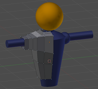
To demonstrate, I'll be using this simple body frame and giving it a shirt.

The first step to creating a shirt to use a ShrinkWrap is to make a rough mesh composition that mimics the general shape of the mesh to be conformed.  In this case, I simply started with a cube, and began extruding [E] and adding ring cuts [Ctrl + r].

You'll notice, that only half the shirt is shown.  Since the character is symmetrical, I'll be using a Mirror Modifier (with clipping) to ensure the shirt is also symmetrical.

An image of the full shirt with mirror enabled, that roughly follows the blue body.

Next we add the ShrinkWrap modifier to the shirt mesh.  Note that the field labeled Target represents the mesh to conform to.  Note also, that it is a single object, so if the body in this example was two meshes (which it was), they would need to be joined [Ctrl + J] first.  Or as an alternative, to keep them independent, a joined duplicate could be made just to create the shirt.

Finally, in the Offset field, this can be adjusted to scale the modified mesh outward (away from the body).

At first glance, the modifier does a somewhat poor job in that much of the blue body protrudes through the shirt, but this is simply because currently, our shirt mesh has so few vertices that the mesh can't conform to all the details of the body.  This works best for convex shapes, and more vertices would be needed to fill holes.

At this stage some manual manipulation is needed to ensure the body doesn't show through the shirt.  You may even find that you need to add more ring-cuts or extrusions to give enough detail to cover the body adequately.

Finally, a Subdivision Surface modifier can be applied to give the shirt a more smooth look.  More massaging of the mesh may be required.

Although there is some tweaking in the process, the ShrinkWrap modifier saves you a lot of time getting the general frame to match the body, than having to do the entire alignment manually.


Wednesday, March 14, 2012

Shadeless

Rendering an object with a Shadeless material essentially allows the full color of the color or texture to visible, without any interaction with the rest of the lighting in the scene.   This is most often used in cases of background images, and with creating color masks within a scene.

In the Blender Internal this is done quite simply by checking the Shadeless box in the Material tool palette (as seen below).

In Cycles, it is a little more cumbersome, and the node setup (below) must be used.  Essentially what's going on here is that the material is set to Emmissive, but to prevent it from lighting other objects in the scene, the light paths are isolated to only casting toward the camera.