This entry aims to summarize some of the commonly-agreed-upon best practices in regards to mesh modeling. The approach of applying intelligence in the design of a mesh is sometime referred to as optimizing the Mesh Topology. To say that a mesh is optimized begs of the question of what it's optimized for. In this case, it's all the big applications of 3D modeling: animation, mesh smoothing, and gaming engine import.
The first topic to discuss in mesh topology is the approach to modeling. The two primary methods are Box Modeling and Polygon Modeling. In box modeling, the modeler starts with a mesh primitive (i.e cube, cylinder or a sphere) and extrudes faces and adds ring cuts and tweaks the mesh until it suits its purpose.

With Polygon Modeling, the modeler works primarily with edges and vertices, to make its creation. This method is much more arduous and intensive, but provides the highest level of control, and allows for much more sophisticated (but efficient) mesh topologies to be created. This is the preferred method for organic shaped models.

In either case, there is one paramount rule that seems to be expressed in many forums, even though there are few exceptions. This rule is that a modeler should avoid using triangles at all costs. There will be exceptions, but quads should be used whenever possible.

Triangles are a nuisance to subsurfacing, to animation, and to creating efficient meshes that are imported into gaming engines. In the case of subsurfing, you are dividing the polygon into smaller pieces, and dividing a 4 by 2 is obviously a cleaner arithmetic than dividing 3 by 2. Using triangles results in unpredictable, or pinched geometry both in subsurfing and in animation. This can easily be seen when a cylinder (with triangles for the capped ends) is subsurfed. In the image below, the ridges at the top are caused by the triangles.

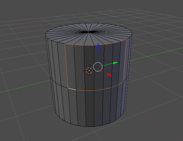
Although the triangles could be removed through some strategic selecting and converting of Tris to Quads [Ctrl + J], a simpler approach which renders the triangles less involved in the subsurf would be to start with uncapped ends, and extrude [E] and scale [S] the top ring to create a ring of quads first, then extruding [E] the ring again, and collapsing [W merge] the final hole. This will make the tesselation between the sides and the top about quads (not tris), and hence the curve will be smooth. The image below shows the difference between the Quads vs Tris approach.

Another example of a primitive that naturally has triangles is the UV Sphere. The image below highlights the ring of triangles similar to the cylinder example. However, there is an easier way to create a sphere without triangles. Start with a cube, select all vertices, and subdivide [W] it a few times. Then, sphereize [Shift + Alt + S] the cube, and you'll get the sphere on the right, with all Quads, but some Poles (which we'll discuss next).

The simplest definition of a Pole is a vertex that does not connect to four edges. Except for cases like the sphere/cylinder, a pole in a quad mesh will have either 3 or 5 vertices. The image below shows an example of a situation where there is a 5 edge pole, and a 3 edge pole.

Note in zoomed out image of this example, the unique effect on edge-loops that occurs. The red set of faces in the mesh represents an edge-loop which is shaped like an 'O'. But notice in the highlighted faces, that edge-loops running up and down and left and right, essentially bypass the red ring. This is the nature of poles and how they allow more complex topologies while maintaining an all-quads mesh.

In conclusion, use the two different modeling methods, Box or Polygon based on the needs of the model. But in any case, always avoid triangles, and use poles to help solve complex mesh situations to maintain an all quads topology.
A great quick video on manipulating mesh topology can be found here: Blender Cookie Tutorial